原文链接:https://www.cnblogs.com/shangdawei/p/4756415.html
NSS分为内部引脚和外部引脚。
NSS外部引脚可以作为输入信号或者输出信号,
输入信号一般用作硬件方式从机的片选,
而输出信号一般用于主SPI去片选与之相连的从SPI。
NSS从设备选择有两种模式:
1、软件模式
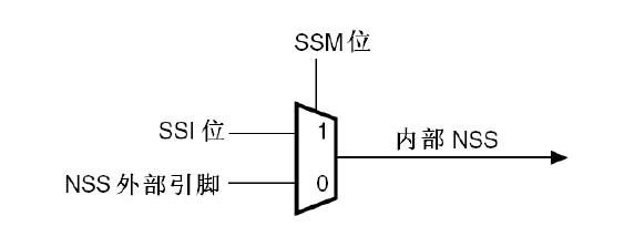
可以通过设置SPI_CR1寄存器的SSM位来使能这种模式,当它为1时,NSS引脚上的电平由SSI决定。
在这种模式下NSS外部引脚可以用作它用,而内部NSS信号电平可以通过写SPI_CR1的SSI位来驱动。
2、硬件模式两种方式:
(1)对于主SPI,NSS可以直接接高电平,对于从SPI,可以直接接低电平。
(2)当STM32F10xxx工作为主SPI,并且NSS输出已经通过SPI_CR2寄存器的SSOE位使能,
这时主机的NSS讲作为输出信号,引脚信号被拉低,所有NSS引脚与这个主SPI的NSS引脚相连
并配置为硬件NSS的STM32F10xxx SPI设备,将自动变成从SPI设备。
此时两个的NSS信号线可以接个上拉电阻直连。
按照标准的SPI协议,当SPI被配置为主机模式后,通过SPI对从设备进行操作时,
其NSS应该自动置低,从而选中(使能)从设备;
一旦不对从设备进行操作,NSS立刻置为高。
但是,我在实际调试过程中却发现:STM32 SPI NSS无法自动实现跳变。
一旦SPI初始化完成并使能SPI,NSS立刻置低,然后保持不变。
这个问题一直无法解决,直到我在ST官方论坛上看到国外有些技术人员也在讨论这个问题,
他们得出的结论是:STM32 SPI NSS无法自动跳变。
ST官方技术人员也证实:
STM32 SPI NSS是不会自动置位和复位的。按照官方说法,ST已经将其列入了改进计划。
对于这个问题,可以采用下面的方法解决:
在SPI初始化时,采用NSS soft模式,然后使能NSS输出功能。
从而将NSS当做GPIO使用,通过软件set和reset来实现NSS的置位和复位。
通过将NSS配置为GPIO,在通过SPI操作从设备时,就可以通过软件来选中和释放从设备了。
虽然比起硬件自动置位要麻烦,但问题毕竟解决了。
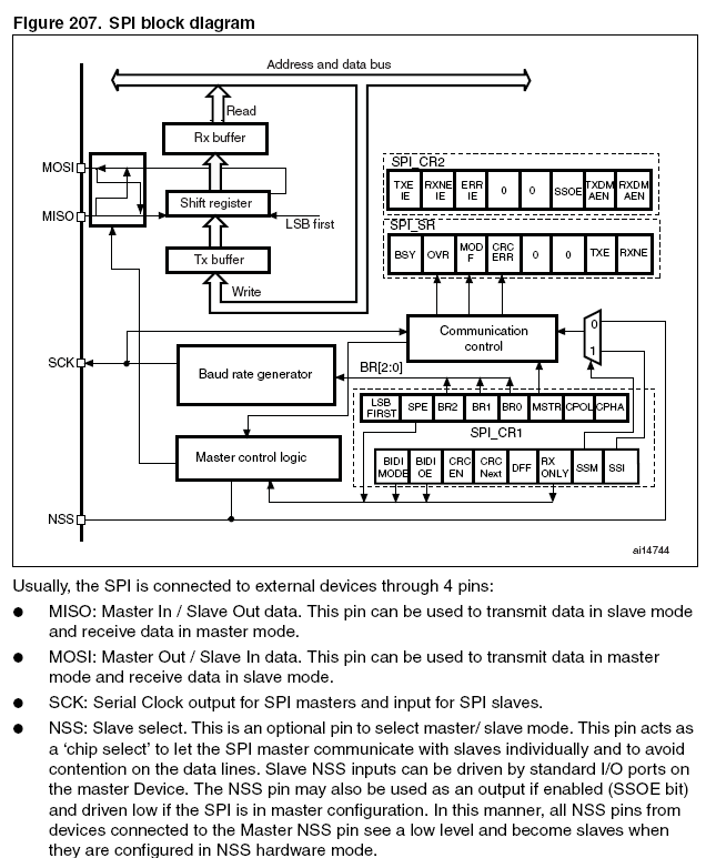
Slave select (NSS) pin management
There are two NSS modes:
● Software NSS mode:
this mode is enabled by setting the SSM bit in the SPI_CR1 register (see Figure 209).
In this mode, the external NSS pin is free for other application uses
and the internal NSS signal level is driven by writing to the SSI bit in the SPI_CR1 register.
● Hardware NSS mode: there are two cases:
– NSS output is enabled:
when the STM32F20xxx is operating as a Master and the NSS output is enabled
through the SSOE bit in the SPI_CR2 register, the NSS pin is driven low and all the NSS pins
of devices connected to the Master NSS pin see a low level
and become slaves when they are configured in NSS hardware mode.
When an SPI wants to broadcast a message, it has to pull NSS low to inform all others
that there is now a master for the bus.
If it fails to pull NSS low, this means that there is another master communicating,
and a Hard Fault error occurs.
– NSS output is disabled: the multimaster capability is allowed.
当SPI配置为hard模式后,通过检测NSS可以实现的是自身主机和从机模式的切换,
而不是大多数人所认为的自动NSS。。。
也就是说:在一个多SPI系统中,STM32 SPI通过NSS检测,一旦发现系统中无NSS低信号,自己就输出低,从而成为主机;
当系统中有NSS低信号时(及已经有其它SPI宣布为主机),自己就配置为从机。
所谓的hard模式的NSS,实际就是为了实现多机间通信的。
STM32 SPI NSS discussion
About the the STM32 SPI NSS problem of explore.
The STM32 SPI Reference Manual in the schematic given as follows:
Accordance with the standard SPI protocol, when the SPI is configured for master mode,
the SPI operation from the device, the NSS should be automatically set low,
so as to select (enable) from the device; Once we do not operate from the device, NSS immediately set is high.
However, I was found in the actual process of debugging:
STM32 SPI NSS does not automatically transition.
Once the the SPI initialization is complete make can SPI NSS immediately set low,
and then remain unchanged.
This problem can not be resolved, some foreign technicians are also discussing this issue
until I see the ST official forum, They concluded: the STM32 SPI NSS can not be automatically transition.
The official ST technicians also confirmed:
the STM32 SPI NSS is not automatically set and reset.According to the official statement,
ST has included in the improvement plan.
For this problem, you can use the following solutions:
SPI initialization the the NSS soft mode, and then enable the NSS output function.
NSS NSS set and reset as GPIO, set and reset by software.
The code is as follows:
/ * SPI1 configuration ---------------------------------------------- -------- * /
SPI_InitStructure.SPI_Direction = SPI_Direction_1Line_Tx;
SPI_InitStructure.SPI_Mode = SPI_Mode_Master;
SPI_InitStructure.SPI_DataSize = SPI_DataSize_8b;
SPI_InitStructure.SPI_CPOL = SPI_CPOL_Low;
SPI_InitStructure.SPI_CPHA = SPI_CPHA_2Edge;
SPI_InitStructure.SPI_NSS = SPI_NSS_Soft; / /
SPI_InitStructure.SPI_BaudRatePrescaler = SPI_BaudRatePrescaler_4;
SPI_InitStructure.SPI_FirstBit = SPI_FirstBit_MSB ;/ / SPI_FirstBit_MSB;
SPI_InitStructure.SPI_CRCPolynomial = 7;
SPI_Init (SPI1, & SPI_InitStructure);

/ * Enable SPI1.NSS as a GPIO * /
SPI_SSOutputCmd (SPI1, ENABLE);

/ * Configure PA.4 (NSS) ----------------------------------------- --- * /
GPIO_InitStructure.GPIO_Pin = GPIO_Pin_4;
GPIO_InitStructure.GPIO_Mode = GPIO_Mode_Out_PP;
GPIO_Init (GPIOA, & GPIO_InitStructure);
can be software selected and released from the device.
Although than the hardware automatically set to trouble, but after all solved.
When the SPI is configured as a hard mode can be achieved by detecting the NSS own host and slave mode switch,
rather than automatically NSS most people think. . .
In other words:
a multi-SPI system STM32 SPI NSS testing, once the system NSS low signal output low, thus becoming the host;
NSS low signal system (and other SPI announced host), configured as a slave.
The so-called hard mode NSS is in fact in order to achieve multi-machine communication.
Summary:
The words too literally scary, Manual must be carefully read.
The STM32 SPI NSS regardless of the configuration for soft or hard are not automatically set, but it is required in most applications. As the ST forum RichardE said: “Everything would be done by the peripheral. Fire and forget.”
Oh, interesting argument: Fire and forget! ~ ~ ~ ~
The STM32 SPI nss Big Secret
Tag: Work, tasks, qq, Author: zxl_maitian Date: 2012-01-06
On the NSS, I have a headache for it for a long time, look at the manual to see the program,
watch videos, see post, I have not completely understood it.
Had a few want to solve it, but died, only to abandon their own written notes.
Also so much concern about the lack of blood, angry, resulting toothache, chapped lips.
Simply a pain. At that time, I really think I may never do not understand.
So forget it. The teacher said, let me do first technology, go pursuit of principle,
but then I took over the ADXL345 acceleration sensor with SPI control task
and a combination of a full-duplex SPI instance, was thus slowly mystery surfaced by learning debugging techniques,
and finally understood. SPI is really complicated, but complex and interesting.
I write as a rookie, I understand the STM32 SPI NSS. I hope you will correct me.
The NSS in the end is how it? The answer is the chip select.
Master and during SPI communication from the device, the device has a CS chip select signal, active low,
we usually must be connected to the NSS from the CS.
But just in general so that we generally understand what’s going on,
a lot of things about the NSS, there are a lot of things, let me explain.
Look at the input and output mode.
Can be entered for each SPI NSS can also output. So-called input the NSS level signal to itself,
the so-called output the NSS level signal sent to the slave.
Configured as an output, or output, we the SSOE bit of through SPI_CR2 register.
SSOE 1 and SPI is in master mode control, NSS output low is pulled low,
the NSS pin so when the other SPI devices connected to it, inevitably received low,
the chip select , have become from the device. The output of the NSS introduced here
The following describes the input of the NSS.
We all know that the NSS input hardware inputs and software is divided into the control input two modes,
then you start from these two modes, to uncover the veil.
Let me talk about the software mode.
1 for SPI master
set SPI_CR1 register SSM and SSI bit the SSM to 1 to
enable software management. NSS internal and external pin.
At this time, the external pin reserved for him (can be used as GPIO driver from the device’s chip select signal).
Internal NSS pin level driven by the register SPI_CRL SSI bit.
SSI bit to 1 in order to enable the NSS level is high.
At this time, can not help but question why the main device’s internal NSS level 1?
STM32 manual, to keep the MSTR and SPE bit is 1, that is to keep the host mode,
only NSS received a high level signal, the two in order to maintain the set that is
to keep the SPI for STM32 the host state, the NSS internal input level must be high.
Of course, here in hardware mode as well.
2 SPI slave
The to host own internal NSS high level resolved, then the SPI chip select active low slave NSS have to solve ah.
If the Slave Select the STM32 an SPI, such as host elected SPI1 slave elected SPI2, will have the following operation
The manual says the NSS pin must be connected to a low-level signal before completing the byte transfer.
The SSM bit software mode, you need to set the SPI_CR1 register (software management enabled)
and SSI bit 0 is really the case. SSI must be 0, which is the SPI2 sheet preferably is low, then the chip select successful.
Slave SPI chip, for example, that the ADXL345 acceleration sensor.
Well, we can There are two ways
A method is the CS of the chip is connected to GND,
another method, a GPIO port to output a low level to control the CS Chip Select success.
This GPIO can be any one GPIO port, of course, we mentioned above SPI Host Configuration software mode,
the external NSS pin reserved for him, it is a GPIO, we can also use it.
At this time, we can set the push-pull output is low,
and then follow the machine line is connected to the CS, then you can chip select from the chip.
Say that the hardware mode.
For the host, the NSS can be connected directly to the high, slave, NSS low.
Of course, we mentioned above, when a host SSOE 1, the master work in output mode,
and NSS is pulled low, we want the slave select, as long as the CS is connected to the host NSS CSautomatically pulled low.
This is ST designed STM32 SPI NSS workflow.
The following examples to introduce.
We introduce a STM32 on SPI1 and SPI2 full-duplex communication procedures,
specific procedures, you can add QQ 843538946 asked me to.
Only describes the the SPI configuration program.
/ * SPI1 Config ———————————————- ————— * /
SPI_InitStructure.SPI_Direction = SPI_Direction_2Lines_FullDuplex;
SPI_InitStructure.SPI_Mode = SPI_Mode_Master, / / set SPI1-based mode, set the SSI 1
SPI_InitStructure.SPI_DataSize = SPI_DataSize_8b;
SPI_InitStructure.SPI_CPOL = SPI_CPOL_Low;
SPI_InitStructure.SPI_CPHA = SPI_CPHA_2Edge;
SPI_InitStructure.SPI_NSS = SPI_NSS_Soft; / / set the SSM, software management
SPI_InitStructure.SPI_BaudRatePrescaler = SPI_BaudRatePrescaler_4;
SPI_InitStructure.SPI_FirstBit = SPI_FirstBit_LSB;
SPI_InitStructure.SPI_CRCPolynomial = 7;
SPI_Init (SPI1, & SPI_InitStructure);
/ * SPI2 Config ———————————————- ————— * /
SPI_InitStructure.SPI_Mode = SPI_Mode_Slave ;/ / set here SPI2 mode SSI
/ / Because SPI2 and SPI1 use the same SPI_InitStructure, so SSM bit is 1
SPI_Init (SPI2, & SPI_InitStructure);
For SPI2 the configuration, and SPI1 with the same structure, just mode should be changed
and SSI on the line, such as software enable, as well as the timing of what do not change.
SuchSPI1 and SPI2 configuration to.
Later you can transfer data.